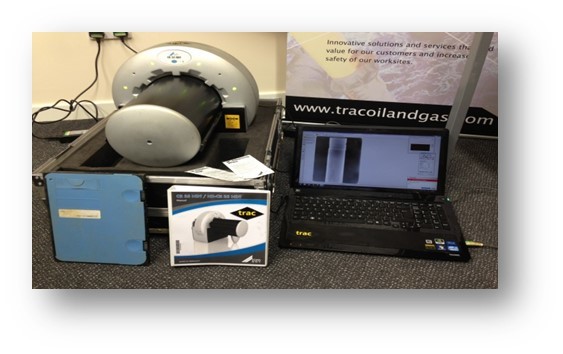
According to GE Measurement & Control Systems, in industrial radiography, X-rays, gamma rays and other types of penetrating radiation are passed through an object and an image is formed using a photographic emulsion.
Interpretation of that image can reveal a lot about the condition of the subject … perhaps a steel pipeline coated in insulation but which is suffering from corrosion, or the quality of a welding job.
It means that penetrating radiation can be utilised in non-destructive examination but that the detection system must be capable of differentiating between different intensities of radiation.
Two important things to keep in mind when viewing a radiographic image are:
• A radiograph is a two-dimensional image of a three-dimensional object. So, you can’t produce a radiographic image using information provided by a single radiograph.
• A defect will only appear as an image in a radiograph if the defect causes a local difference in radiation absorption.
Sealed sources
The first gamma ray emitting radioisotopes to be used in industrial radiography were naturally occurring radioactive materials like radium.
Such sources were not sealed and so there was a danger of exposure to alpha and beta particles, both of which are extremely damaging to human tissue.
Coupled with this was the even greater hazard of radioactive contamination of the human body.
All gamma sources in use today are man-made. They are manufactured by neutron bombardment of non-radioactive raw materials in the core of a small nuclear reactor.
The sources in use are all beta emitters – gamma rays being produced as a by-product of beta emission. To prevent beta emission or contamination hazard the sources used in industrial radiography are invariably sealed sources.
The fissile material is encapsulated in a high integrity titanium or stainless steel shell.
Beta radiation is not capable of penetrating the walls of the capsule, and the capsule further precludes any possible contamination hazard as long as it remains intact.
Methods of producing a radiographic image
It basically boils down to the use of film and digital technologies.
Film
Radiographic film is essentially the same as that used in photography in that it consists of a suspension of silver halide grains in a gelatine binder on an acetate or polyester base. A crucial difference is that radiographic film has a thicker emulsion.
Two types of radiographic film are used for industrial radiography:
• Direct type film, where the principal cause of image formation is the ionising radiation itself. This may be coupled with the effect of “secondary electrons” emitted from metallic foil intensifying screens.
• Screen type film, where the principal cause of image formation is light emitted from fluorescent-image-intensifying screens under the action of ionising radiation.
Digital
The introduction of microprocessors and computers has brought about significant changes to radiographic examination.
The driving force was the medical field where digital radiography has become standard technology.
Digital radiography partly replaces conventional film and also permits new applications. The growing number of available standards, norms, codes and specifications – essential for industrial acceptance and application – supports this tendency.
Digitisation of traditional radiographs, although not real digital radiography, uses the same digitisation technology, presentation on a display of a work station and image adjustment.
Digitisation of film is done for the purpose of archiving and image enhancement.
The major merits of digital radiography compared to conventional film are:
• Shorter exposure times and thus potentially safer
• Faster processing
• No chemicals, therefore no environmental pollution
• No consumables therefore low operational costs
• Plates, panels and flat beds can be used repeatedly
• A very wide dynamic exposure range/latitude therefore fewer re-takes
• Possibility of assisted defect recognition (ADR)
But, despite all of these positive features, the image resolution of even the most optimised digital method is still not as high as can be achieved with fine grain film.
Digging a bit deeper, there is an option that uses storage phosphor plates and is known as “computed radiography” or CR for short.
This filmless technique is an alternative for the use of medium to coarse grain X-ray film.
In addition to having an extremely wide dynamic range compared to conventional film, CR technique is much more sensitive to radiation, thus requiring a lower dose. This results in shorter exposure times and a reduced controlled area (radiation exclusion zone).
Then there is two-step digital radiography where the image is not formed directly, but through an intermediate phase, as is the case with conventional X-ray film.
Typical Oil and Gas Applications
These particularly include the detection of corrosion under insulation (CUI) on process pipework and corrosion under pipe supports (CUPS).
CUI is an unpredictable corrosion mechanism that can occur anywhere in insulated pipework and other components such as vessels found on many oil and gas sites both off and onshore.
Quite simply, corrosion is insidious and well known to be a challenging form of degradation to reliably detect using NDT methods.
CUPS is also a commonplace degradation problem. It too has proven to be a major industry challenge over the years.
