Capacitive Imaging of Corrosion under Composite Repair Wraps
The offshore oil & gas industry requires an inspection technique that accurately determines condition of pipe surfaces under composite repair wraps which can, in certain conditions, provide a “breeding ground” for corrosion.
There are many different types of non-destructive inspection techniques that are routinely used in the offshore industry. Among the most common are ultrasound, X-rays, dye-penetrant and eddy current inspection.
But all have downsides when it comes to assessing the condition of composite repair wrapped pipework.
However, Capacitive Imaging (CI) might represent a potential solution to this problem as it can identify corrosion-induced defects in the pipe’s structure.
The University of Strathclyde and TRAC Oil & Gas Ltd are collaborating on a project aimed at proving the concept of CI for corrosion mapping, the project being supported by the Centre Sensor and Imaging Systems (CENSIS) in partnership with the Oil & Gas Technology Centre (OGTC).
Objective
The objective of the presented study is to establish capability of Capacitive Imaging to non-destructively determine wall loss of steel pipes under composite repair wraps.
What is Capacitive Imaging?
Capacitive Imaging is based on the use of coplanar contiguous electrodes with applied potential difference to scan surfaces of inspected structures. CI has a demonstrated capability to detect defects in a broad range of materials: plastics, glass fibre and carbon fibre composites, plus metallic as well as concrete structures.
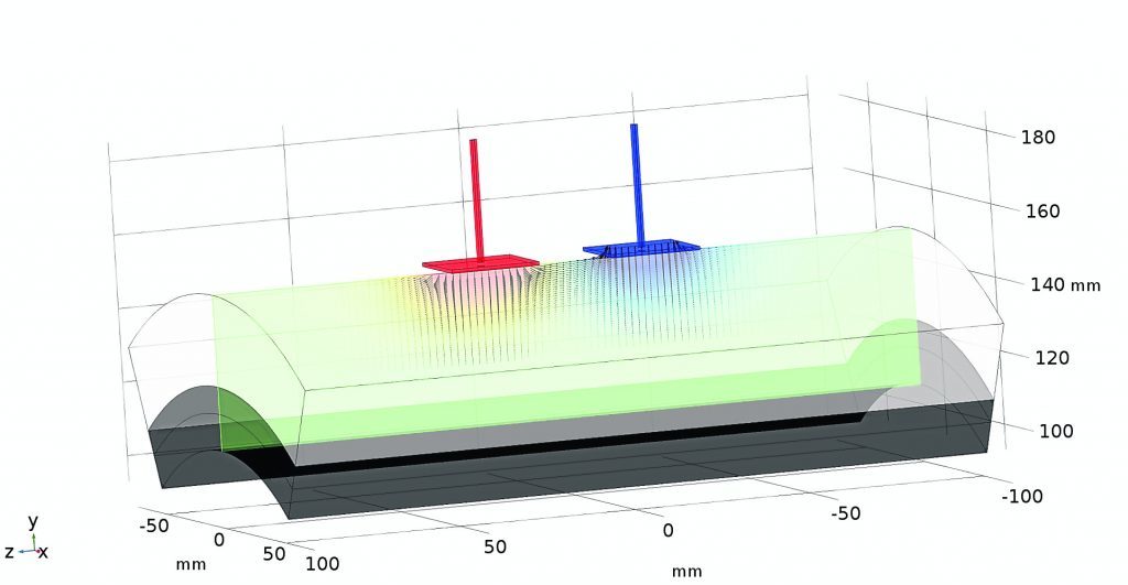
Figure 1 illustrates principles of capacitive imaging. The red electrode has a positive applied electric potential while the blue electrode has a negative applied electric potential.
Each electrode features a square plate sided 25mm, while the distance between the two electrodes of 20mm.
The dark grey solid represents a section of carbon steel pipe. This has an external diameter of 250mm and wall thickness of 12.5mm.
The white solid area in the image represents a repair wrap of 50mm thickness.
The greenish “colour map slice” in axis-radial plane shows distribution of electric potential in the repair wrap.
However, in locations where corrosion processes continued under the wrap, the distance to the metallic pipe wall will change. This in turn will affect the overall capacitance of the system.
Likewise, where there are voids or other defects in the repair wrap, there are local dielectric constant changes which also result in the change of the capacitance of the system.
Applying high frequency alternating current CI will induce alternating magnetic field below the planar capacitor which in turn will generate eddy currents in the pipe wall.
Magnetic field due to the eddy currents will cause change of the impedance of the entire system.
Therefore CI can be sensitive not only to defects in the dielectric repair wrap, but also to defects in the pipe.
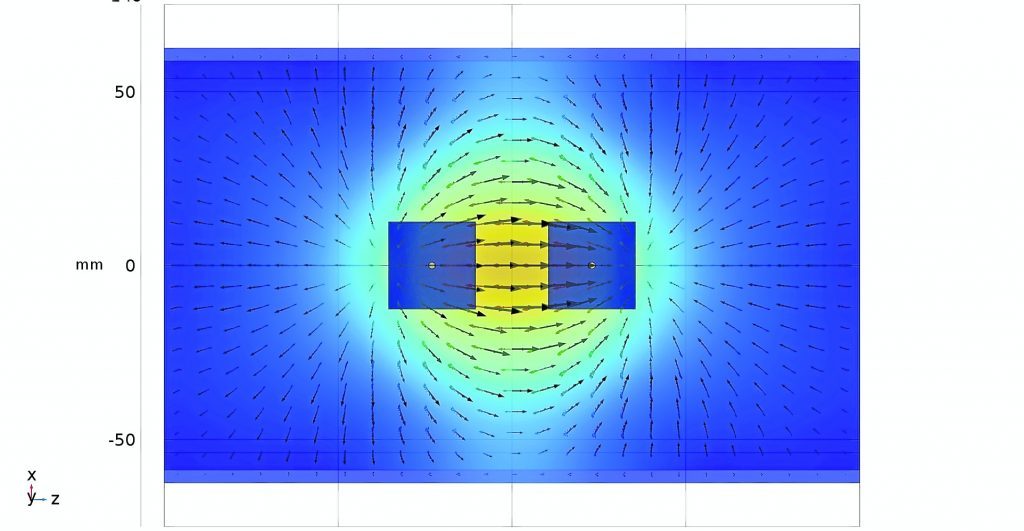
Figure 2 shows eddy currents induced in the pipe wall by an AC excitation voltage applied to the electrodes.
The theoretical results will then be used to design and manufacture an appropriate sensor to be trialled on relevant samples replicating the work to be carried out in-situ.
